2. 华北电力大学 核热工安全与标准化研究所 北京 102206;
3. 华北电力大学 非能动核能安全技术北京市重点实验室 北京 102206;
4. 南华大学 核科学技术学院 衡阳 421001;
5. 核反应堆系统设计技术国家级重点实验室 成都 610041
2. Nuclear Safety and Thermal Power Standardization Institute, North China Electric Power University, Beijing 102206, China;
3. Beijing Key Laboratory of Passive Safety Technology for Nuclear Energy, North China Electric Power University, Beijing 102206, China;
4. College of Nuclear Science and Technology, University of South China, Hengyang 421001, China;
5. State Key Laboratory of Reactor System Design Technology, Chengdu 610041, China
反应堆在运行过程中,由于流体对结构材料的腐蚀冲刷、磨蚀-腐蚀、管道流体加速腐蚀(Flow Accelerated Corrosion, FAC)效应[1-2]等的影响。蒸汽发生器两侧的流体中都会出现不溶性腐蚀产物,腐蚀产物在流动通道中的迁移会加速结构材料腐蚀,同时使得这些不溶性产物具有放射性。在发生蒸汽传热管破裂事故时,不溶性腐蚀产物随着高温高压流体一起进入蒸汽发生器二次侧。对二次侧材料产生冲击,造成二回路结构材料的加速磨损,同时可能导致放射性绕过安全壳而进入大气或凝汽器。对蒸汽发生器传热管破裂事故的研究已经比较多。但大多集中在对其流动特性[3-4]、对堆芯换热特性[5-6]的影响以及故障处理[7]方面。对空气中颗粒物沉积的研究已经比较完善,周涛等[8]对窄通道内的PM2.5的速度分布和颗粒沉积规律进行了理论计算。Barrett等[9]研究了电场对放射性颗粒运动的影响。叶杰等[10]对AP1000多根蒸汽发生器传热管破裂进行了分析。华北电力大学核热工安全与标准化研究所的杨旭等[11]对不溶性粒状腐蚀产物在压水堆堆芯内的沉积进行了研究。针对蒸汽传热管破裂事故中的颗粒物进行的研究尚未发现。因此对蒸汽发生器传热管破裂事故中颗粒行为进行研究是有意义的。
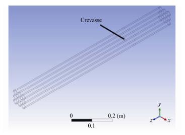
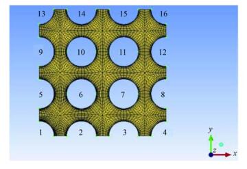
1 研究对象几何模型如图 1所示,根据大亚湾核电站蒸汽发生器(法国55/19型)传热管实际尺寸建模,蒸汽传热管外径19.05 mm,中心距27.05 mm,模型长度为1 000 mm。为使模拟尾部充分发展,而又不受入口段影响,破口位于1号管,距离模型底端240mm处。破口为朝向6号管的周向破口,破口尺寸8 mm×14 mm。图 2是模型截面网格示意图。计算为破口发生且达到稳定后的稳态,二次侧流体速度0.2 m∙s-1,入口温度为533 K,壁面温度552 K。破口喷放使用速度入口和自由出口。
|
图 1 几何模型 Figure 1 Geometric model. |
|
图 2 截面网格 Figure 2 Section gridding. |
对几何模型采用六面体网格划分,对壁面边界层和破口附近网格进行加密;网格敏感性分析后,从精度和效率上综合考虑,确定网格数为376 048。
模拟过程选用不锈钢作为颗粒材料,粒径2 μm。颗粒在流场中考虑重力、热泳力等。计算雷诺数超过2 320,从而判定流动状态为紊流。采用k-ε模型预测流场变化。多相流模型选择§2.3中的混合模型处理相变。
2 计算模型 2.1 混合k-ε模型混合湍流k-ε模型默认是多相湍流模型,它是单相k-ε模型的延伸,当各相之间密度比接近1时,它适用于相分离的多相流。蒸汽发生器内的两相流没有明确的分界,在计算中编制了相变用户自定义函数(User Defined Function, UDF)以适用计算。k-ε模型是湍动能的方程加上湍动能耗散率的ε方程得到的,统一起来就叫做k-ε模型。在k-ε模型中,湍动能耗散率定义为:
| $ \varepsilon = \frac{\mu }{\rho }\overline {\left( {\frac{{\partial {u_{\rm{i}}}}}{{\partial x_k}}} \right)\left( {\frac{{\partial {u_{\rm{i}}}}}{{\partial x_k}}} \right)} $ | (1) |
这样,湍流粘度μt可以表示成湍动能k和湍动能耗散率ε之间的函数:
| $ {\mu _{\rm{t}}} = {\rho _{\rm{m}}}{C_\mu }\frac{{{k^2}}}{\varepsilon } $ | (2) |
混合k-ε模型的输运方程为:
| $ \begin{array}{l} \frac{\partial }{{\partial t}}{\rho _{\rm{m}}}k + \nabla \cdot {\rho _{\rm{m}}}{\overrightarrow u _{\rm{m}}}k = \\ \begin{array}{*{20}{c}} {}&{} \end{array}\nabla \cdot \left( {\frac{{{\mu _{{\rm{t,m}}}}}}{{{\sigma _k}}}\nabla \cdot k} \right) + {G_{k{\rm{,m}}}} - {\rho _{\rm{m}}}\varepsilon + I{I_{{k_{\rm{m}}}}} \end{array} $ | (3) |
| $ \begin{array}{l} \frac{\partial }{{\partial t}}\left( {{\rho _{\rm{m}}}\varepsilon } \right) + \nabla \cdot \left( {{\rho _{\rm{m}}}{{\overrightarrow u }_{\rm{m}}}\varepsilon } \right) = \\ \begin{array}{*{20}{c}} {}&{} \end{array}\nabla \cdot \left( {\frac{{{\mu _{{\rm{t,m}}}}}}{{{\sigma _\varepsilon }}}\nabla \varepsilon } \right) + \frac{\varepsilon }{k}\left( {{C_{1\varepsilon }}{G_{k{\rm{,m}}}} - {C_{2\varepsilon }}{\rho _{\rm{m}}}\varepsilon } \right) + I{I_{{\varepsilon _{\rm{m}}}}} \end{array} $ | (4) |
式中:μ为流体动力粘度,Pa∙s;ρ为流体密度,kg∙m-3;ρm是混合密度,kg∙m-3;混合速度um,m∙s-1;IIkm和IIεm是源项;μt, m表示平均湍流粘度,Pa∙s;Cμ、C1ε和C2ε为经验常量;Gk, m为层流速度梯度产生的湍流动能,J。
2.2 离散相轨道计算模型FLUENT通过求解拉氏坐标下颗粒作用力微分方程来求解离散相颗粒的轨迹。颗粒的平衡方程在笛卡尔坐标系下的形式为:
| $ \frac{{{\rm{d}}{u_{\rm{p}}}}}{{{\rm{d}}t}} = {F_{\rm{D}}}\left( {u - {u_{\rm{p}}}} \right) + \frac{{{g_x}\left( {{\rho _{\rm{p}}} - \rho } \right)}}{{{\rho _{\rm{p}}}}} + {F_x} $ | (5) |
式中:FD(u-up)为颗粒的单位质量曳力,N∙kg-1;u为流体相速度,m∙s-1;up为颗粒速度,m∙s-1;ρ为流体密度,kg∙m-3;ρp为颗粒密度(骨架密度),kg∙m-3;gx是颗粒在x方向的重力加速度,m∙s-2;Fx是颗粒平衡方程中的其他作用力,N∙kg-1。对于粒径为1-10μm的颗粒,Stokes'曳力公式是适用的。这种情况下,FD定义为:FD=18μ/dp2ρpCc,dp为颗粒直径,m;系数Cc为Stokes'曳力公式的Cunningham修正常数(考虑稀薄气体力学的颗粒壁面速度滑移的修正),Cc=1+2λ[1.257+0.4exp(-1.1dp/2λ)]/d,λ为气体分子平均自由程,m。
2.3 混合模型混合模型是描述连续流动系统中的宏观运动状况的物理模型。它假设小尺寸空间范围内出于局部平衡,可以用于各相之间流速不同的多相流计算,也可以用于具有很强的耦合及相变的均匀多相流模型的计算。
混合模型的连续性方程、动量方程以及能量方程可以表述为:
| $ \frac{\partial }{{\partial t}}({\rho _{\rm{m}}}) + \nabla \cdot ({\rho _{\rm{m}}}{u_{\rm{m}}}) = 0 $ | (6) |
| $ \begin{array}{l} \frac{\partial }{{\partial t}}\left( {{\rho _{\rm{m}}}{u_{\rm{m}}}} \right) + \nabla \cdot \left( {{\rho _{\rm{m}}}{u_{\rm{m}}}{u_{\rm{m}}}} \right) = - \nabla p + \\ \begin{array}{*{20}{c}} {}&{} \end{array}{\rho _{\rm{m}}}g + F + \nabla \cdot \left[ {{\mu _{\rm{m}}}\left( {\nabla {u_{\rm{m}}} + \nabla {u_{\rm{m}}}^T} \right)} \right] + \\ \begin{array}{*{20}{c}} {}&{} \end{array}\nabla \cdot \left( {\sum\limits_{k{\rm{ = 1}}}^n {{\alpha _k}{\rho _k}{u_{{\rm{dr,}}k}}{u_{{\rm{dr,}}k}}} } \right) \end{array} $ | (7) |
| $ \begin{array}{l} \nabla \cdot \sum\limits_{k{\rm{ = 1}}}^n {\left( {{\alpha _k}{u_k}\left( {{\rho _k}{E_k} + p} \right)} \right)} = \\ \begin{array}{*{20}{c}} {}&{} \end{array}\nabla \cdot \left( {{k_{{\rm{eff}}}}\nabla T} \right) + {S_{\rm{E}}} - \frac{\partial }{{\partial t}}\sum\limits_{k{\rm{ = 1}}}^n {\left( {{\alpha _k}{\rho _k}{E_k}} \right)} \end{array} $ | (8) |
式中:μm是平均粘度,Pa∙s;g是重力加速度,m∙s-2;αk是k相质量分数;ρk是k相密度,kg∙m-3;udr, k是k相相对主流滑移速度,m∙s-1;F是体积力,N∙m-3;keff是有效热传导率,W∙m-1∙K-1;T是温度,K;Ek是k相动能,J;p是压强,Pa;SE包含了所有体积热源,J∙m-3。
2.4 颗粒相和连续相物性模型颗粒相来源于反应堆运行时流体对结构材料的冲刷腐蚀等,因此选取不锈钢作为颗粒物,不锈钢物性用Mills等[12]的研究结果,水和水蒸气物性用Wagner等[13]的研究结果。假定颗粒物浓度为1×10⁻⁴kg∙s-1,速度为0.1 m∙s-1。
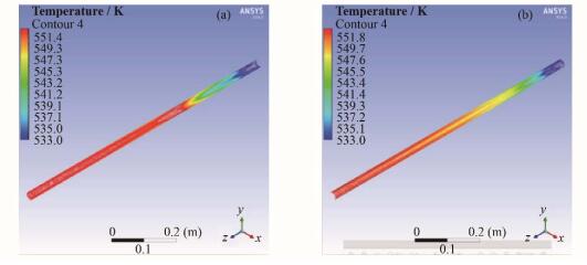
3 数值模拟结果与分析 3.1 温度分布 3.1.1 轴向温度分布图 3为二次侧破口周围传热管附近的轴向流体温度分布,即图 2中的管6二次侧两侧流体的轴向温度分布。图 3分别为靠近破口侧和远离破口侧的流体温度分布。
|
图 3 破口侧管温度(a)和破口远侧管温度(b) Figure 3 Near the crevasse (a) and removed (b) side's temperature. |
从图 3可以看到,轴向位置上流体温度随着高度而增加。在破口附近,由于高温流体的喷入,二次侧流体温度会迅速抬升。对比图 3(a)和(b)发现,在较远的地方温度升高的速度会比近的地方低。同时图 3(b)中高温区明显比图 3(a)中的位置要低,这是喷入的流体在径向移动的过程中,热量向着下面的低温区传递引起的。
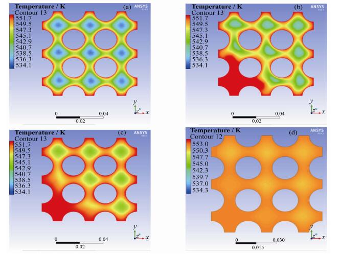
3.1.2 径向温度分布图 4为蒸汽发生器二次侧在蒸汽传热管破裂事故发生时z=0.2 m、z=0.28 m、z=0.4 m和z=0.9 m处的流场温度分布。
|
图 4 z=0.2 m (a)、z=0.28 m (b)、z=0.4 m (c)、z=0.9 m (d)处温度场 Figure 4 z=0.2 m (a), z=0.28 m (b), z=0.4 m (c), z=0.9 m (d) temperature field. |
从图 4(a)中可以看到,在破口以下z=0.2 m处,每个换热单元之间的温度分布基本一致,都是在壁面附近的温度较高,而流动中心较低。这是因为蒸汽发生器一次侧流动的流体温度高于二次侧,导致壁面温度要比二次侧流体高。在破口附近(图 4(b),z=0.28 m),高温高压流体迅速喷射而出,在破口附近形成高温区,并且在破口附近还存在流体温度高于壁面温度的情况,这将严重影响蒸汽发生器的换热特性。随着轴向位置的抬升(图 4(c)和(d),即z=0.4m和z=0.9 m处),破口的影响开始扩大,高温区开始向着较远的管道扩散。但是整体的最高温度开始下降。在出口附近,温度分布已经再次趋于均匀,但是整体上温度明显高于破口以下。较高的温度会减小一次侧与二次侧的温差,从而影响其他管道的换热特性,导致堆芯热量不能及时移除。
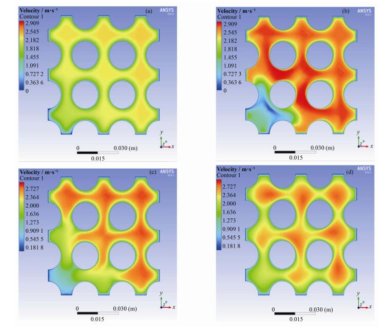
3.2 速度分布 3.2.1 轴向速度分布图 5分别为蒸汽发生器二次侧在蒸汽传热管破裂事故发生时z=0.2 m、z=0.28 m、z=0.4 m和z=0.9m处的轴向流体速度分布。
|
图 5 z=0.2 m (a)、z=0.28 m (b)、z=0.4 m (c)、z=0.9 m (d)处速度场 Figure 5 z=0.2 m (a), z=0.28 m (b), z=0.4 m (c), z=0.9 m (d) axial velocity field. |
从图 5(a)可以看到,在破口以下z=0.2 m处,每个冷却单元的温度分布基本相同,都是流动中心速度较大,而壁面附近由于边界层的影响而速度较低。在破口附近(图 5(b),z=0.28 m),从破口来的高速流体迅速冲入二次侧,打乱原来稳定的流场,导致远离破口的地方流速增加。而在破口上方,由于轴向流动的流体被高速流体携带到远离破口的地方而导致流速下降(图 5(b)和(c),管1附近)。随着流动的进行,破口的影响开始减弱,流场逐渐恢复(图 5(c)、(d))。但整体的流速要高于破口下端。
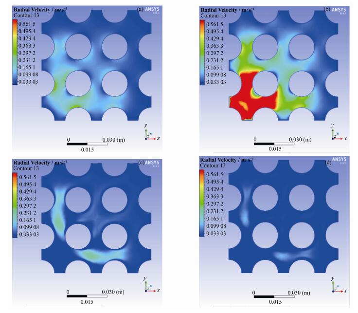
3.2.2 径向速度分布图 6为蒸汽传热管破裂事故时z=0.2 m、z=0.28m、z=0.4 m和z=0.9 m处的径向速度分布。
|
图 6 z=0.2 m (a)、z=0.28 m (b)、z=0.4 m (c)、z=0.9 m (d)径向速度 Figure 6 z=0.2 m (a), z=0.28 m (b), z=0.4 m (c), z=0.9 m (d) radial velocity field. |
从图 6(a)可以看出,在破口下方z=0.2 m,由于破口的影响也存在较强的径向速度分布。图 6(b)中,破口高速流体冲入二次侧导致在破口中心附近存在较大的径向速度场,特别是临近破口的传热管间距最小处的速度较大。而正对着的部分由于存在滞止现象,速度在该区域分布不是最大的。在高速流场区域,颗粒物随着流场运动将会对壁面产生磨损。磨损与速度和切入角度相关,在破口处速度和角度最大,所以破口附近的径向壁面磨损最严重。图 6(c)和(d)可以看出,打乱的流场随着轴向位置的抬升在逐渐恢复,径向速度分布逐渐均匀化。
3.3 破口附近壁面应力分布图 7为破口附近壁面的应力分布。图 7中,在破口附近,面向破口的壁面压应力明显高于其他位置的壁面压力,而背向破口的壁面压应力较低。而在破口上方,压应力反而较低,出现一个低压应力区域。破口附近应力分布的不均匀性将会影响传热管的结构性能。

|
图 7 破口附近壁面应力 Figure 7 Stress distribution near the rupture. |
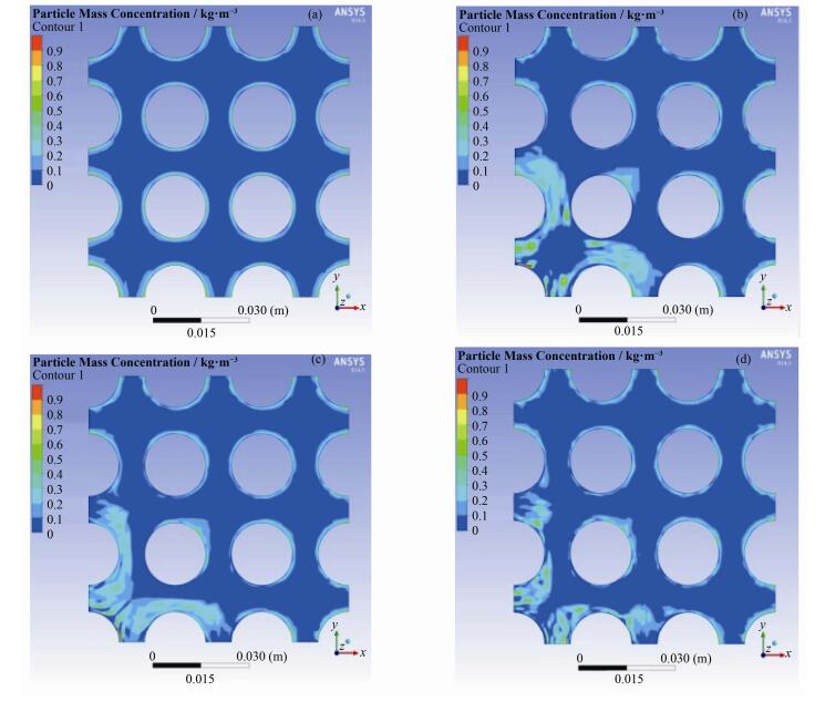
轴向不同位置z=0.2 m、z=0.28 m、z=0.4 m和z=0.9 m处的颗粒物浓度分布情况如图 8所示。从图 8(a)可以看出,在破口以下位置,z=0.2 m处,各个冷却单元的颗粒物浓度分布基本一致,都是在壁面附近较高而流动中心较低。在破口附近z=0.28 m(图 8(b))处,高温流体高速冲入二次侧,使破口附近水迅速汽化,同时由于一次侧的流体中也含有颗粒物,造成颗粒物的高浓度区域。这些高浓度颗粒物的流体向上运动,形成在破口上方传热管壁面附近的高浓度颗粒物区域(图 8(c)、(d))。而且由于在上方附近存在漩涡(图 8(a)),z=0.4,即图 8(c)的颗粒物浓度要高于z=0.28(图 8(b))和z=0.9 m(图 8(d))。从图 7(b)和(c)中可以看出,该区域是破口流体导致横流的背压区,该区速度较低,因此,导致图 8(b)、(c)、(d)所示背离破口的壁面颗粒物浓度明显高于面向破口的颗粒物浓度。
|
图 8 0.2 m (a)、0.28 m (b)、0.4 m (c)、0.9 m (d)颗粒物浓度 Figure 8 0.2 m (a), 0.28 m (b), 0.4 m (c), 0.9 m (d) particle concentration. |
以大亚湾蒸汽发生器为原型建模,利用FLUENT流体软件对蒸汽传热管破裂事故发生时的颗粒物行为进行研究,得到流场温度、速度以及颗粒物浓度分布图。
1) 高温高压的高速流体冲入蒸汽发生器二次侧,在破口附近形成高温场、高速度场及高浓度场。
2) 温度场与速度场随着高度的抬升可以逐渐恢复其均匀性,但是在破口上方的值明显高于下方。
3) 在破口附近上方及背离破口的壁面附近是颗粒物的高浓度区域,颗粒物随着流场运动,会对途经的壁面产生磨蚀作用,从而加速二次侧腐蚀。
| [1] |
Rokuro Nishimura, Yasuaki Maeda. SCC evaluation of type 304 and 316 austenitic stainless steels in acidic chloride solutions using the slow strain rate technique[J]. Corrosion Science, 2004, 46: 769-785. DOI:10.1016/j.corsci.2003.08.001 |
| [2] |
束国刚, 薛飞, 遆文新, 等. 核电厂管道的流体加速腐蚀及其老化管理[J]. 腐蚀与防护, 2006, 27(2): 72-76. SHU Guogang, XUE Fei, TI Wenxin, et al. Flow accelerated corrosion and aging management in nuclear power plants[J]. Corrosion & Protection, 2006, 27(2): 72-76. DOI:10.3969/j.issn.1005-748X.2006.02.006 |
| [3] |
Pra C L D, Velasco F J S, Herranz L E. Simulation of a gas jet entering the secondary side of a steam generator during a SGTR sequence:validation of a FLUENT 6.2 model[J]. Nuclear Engineering and Design, 2010, 240(9): 2206-2214. DOI:10.1016/j.nucengdes.2009.11.021 |
| [4] |
蒋兴, 张明, 谢永诚, 等. 蒸汽发生器二次侧流场三维数值模拟[J]. 原子能科学技术, 2008, 42: 438-443. JIANG Xing, ZHANG Ming, XIE Yongcheng, et al. Three-dimensional numerical simulation of secondary side flow field in steam generator[J]. Atomic Energy Science and Technology, 2008, 42: 438-443. |
| [5] |
Herranz L E, Pra C L D, Velasco F J S. Preliminary steps toward assessing aerosol retention in the break stage of a dry steam generator during severe accident SGTR sequences[J]. Nuclear Engineering and Design, 2008, 238: 1392-1399. DOI:10.1016/j.nucengdes.2007.10.007 |
| [6] |
Herranz L E, Velasco F J S. Characterization of a gas elliptic jet in a nuclear safety scenario[J]. Experimental Thermal and Fluid Science, 2013, 44: 374-384. DOI:10.1016/j.expthermflusci.2012.07.009 |
| [7] |
Jimenez G, Queral C, Rebollo-Mena M J, et al. Analysis of the operator action and the single failure criteria in a SGTR sequence using best estimate assumptions with TRACE5.0[J]. Annals of Nuclear Energy, 2013, 58: 161-177. DOI:10.1016/j.anucene.2013.02.023 |
| [8] |
Zhou T, Yang R C, Wang S C, et al. Visual experiment research of the inhaled particle thermophoresis deposition rule in rectangle turbulent flow tube[J]. Applied Thermal Engineering, 2009, 29(5-6): 1138-1145. DOI:10.1016/j.applthermaleng.2008.06.018 |
| [9] |
Barrett J C, Clement C F, Virdee A B S. The removal of radioactive aerosols by electric fields[J]. Journal of Aerosol Science, 2009, 40(3): 185-192. DOI:10.1016/j.jaerosci.2008.10.004 |
| [10] |
叶杰, 蔡伟, 陈文虎. AP1000多根蒸汽发生器传热管破裂分析[J]. 原子能科学技术, 2015(6): 1057-1061. YE Jie, CAI Wei, CHEN Wenhu. Analysis of multiple steam generator tube rupture for AP1000[J]. Atomic Energy Science and Technology, 2015(6): 1057-1061. DOI:10.7538/yzk.2015.49.06.1057 |
| [11] |
杨旭, 周涛, 汝小龙, 等. 不溶性粒状腐蚀产物在压水堆堆芯内沉积的数值模拟[J]. 核科学与工程, 2014, 34(3): 337-342. YANG Xu, ZHOU Tao, RU Xiaolong, et al. Simulation study on insoluble granular corrosion products deposited in PWR core[J]. Nuclear Science and Engineering, 2014, 34(3): 337-342. |
| [12] |
Mills K C, Su Y C, Shu Z, et al. Equations for the calculation of the thermo-physical properties of stainless steel[J]. ISIJ International, 2004, 44(10): 1661-1668. DOI:10.2355/isijinternational.44.1661 |
| [13] |
Wagner W, Cooper J R, Dittmann A, et al. The IAPWS industrial formulation 1997 for the thermodynamic properties of water and steam[J]. Journal of Engineering for Gas Turbines and Power, 2000, 122(1): 150-182. DOI:10.1115/1.483186 |


