Influence of Partial Coherent Light on the Transmission Spectrum and Goos-Hänchen Shift in Rydberg Atomic Medium
Ali Dilawar, Umer Iftikhar Muhammad, Abbas Muqaddar, Ziauddin
Quantum Optics Laboratory, Department of Physics, COMSATS University, Islamabad, Pakistan


† Corresponding author. E-mail: ziauddin@comsats.edu.pk

Abstract
Abstract

A cold atomic medium (Rydberg medium) with cascade configuration under the blockade mechanism is considered. A partial coherent light (PCL) beam is incident on the medium, which makes an angle θ with z-axis. We study the influence of PCL field on the transmission spectrum and find high transmission of probe field for PCL field. Conversely, it is investigated that the transparency of probe field decrease for coherent light field. The transmission of probe field is also studied via beam width of PCL field and investigated high transmission of probe field for small beam width and vice versa. Interestingly, the Goos-Hänchen shift (GHS) in the transmitted light (TL) is studied for PCL field. Large negative and positive GHS in the TL are investigated for PCL field and small beam width of PCL field.

1. Introduction

A state which has a high principle quantum number is known as Rydberg state.[1] The most important characteristic of Rydberg atom is the strong interaction of one Rydberg atom to the other. For such a strong interaction, only one excited Rydberg atom can suppress the other excitation of Rydberg atoms in a small volume, which is known as dipole blockade.[2] To address electromagnetically induced transparency (EIT) in atomic system, the Rydberg states have exhibited important characteristics such as strong dipole-dipole interactions, long radiative life time as well as the van der waals (vdW) interactions.[3] The characteristics of highly Rydberg excitations have significant role in information processing as well as in quantum gates,[46] many body effects,[79] and light atom quantum interface.[1012]

In the above investigations, major part is dependent on the dipole blockade phenomenon.[1314] In earlier studies, it has been revealed that the blockade phenomenon of Rydberg atom becomes a good candidate for devices like single photon sources, single photon switches, and photon filters.[1517] Earlier, an experiment has been done in which a strong vdW interaction has been considered in atomic Rydberg medium.[18] In the experiment, a reduction in the transmission spectrum has been observed via increasing the intensity of input probe field. The authors of this experiment have no clear evidence of the reduction of transmission spectrum via increasing the probe field intensity. Later, this erratic reduction of the transmission spectrum via increasing the probe field intensity has been explained by considering a theoretical model based on the blockade phenomenon.[19] Further, the transmission of probe field has been studied in optomechanical systems.[2021] and investigated enhanced generation of higher-order side bands.

In addition, the Goos-Hänchen shift (GHS) is a process when a light experiences a tiny displacement (shift) in the phenomenon of total internal reflection. This tiny shift has been observed by Goos and Hänchen[22] in total internal reflection in the interface of two media. After the observation of Goos and Hänchen, the GHS has been studied in different structure.[2330] The GHS has been emerged substantial interests due to its potential applications in optical sensing such as measurement of the refractive index, beam angle, irregularities and roughness of the surface of a medium.[28] In last couples of years, the GHS has been investigated by considering atomic media and quantum well systems in a cavity.[3138]

We consider an atomic medium consists of three-level Rydberg atoms and study the effect of PCL field on the transmission spectrum. The motivation comes from earlier investigations[1819] where a coherent light has been used and studied the transmission of probe field through Rydberg atomic medium. In some other investigations,[3941] the GHS and diffraction grating have been studied using PCL field. In the present work, we expect high transmission of probe field for PCL while low transmission for coherent light. Similarly, we also expect giant GHS in the TL for PCL field.

2. Model

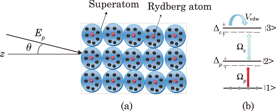
We consider a light beam having a mode index m falls on the atomic ensemble of Rydberg atoms as shown in see Fig. 1(a). The required electric field equation can be written as
where
represents the angular spectrum for a proposed PCL beam, which can be calculated by taking the Fourier transform of , whereas Hm represents the Hermite polynomials and ky is the wave vector of the y component. Here, ws and wg are the beam width and spectral coherence width of partially coherent light beam, respectively. Similarly, c can be defined as where . The expression for probe field transmission can be expressed as
In order to investigate the GHS in the TL, we use the stationary phase theory where for the incident beam i.e, Eq. (1) has large width and narrow angular spectrum that can be represented as[3132]
where is the phase of the transmission coefficient. Further, we can also represent the above expression in the form as
where θ be the incident angle.

Fig. 1. (Color online) (a) Schematics of PCL beam incident on a medium; (b) the energy-level configuration of a three-level Rydberg atom.
2.1. Atom-Field Interaction

We consider an atomic medium where each atom consists of cold rubidium (87Rb) atoms in a cascade configuration. The medium is interacting with probe and control fields as shown in Fig. 1(b). The energy-level of each atom can be represented by , , and . A probe field is applied between and having Rabi frequency whereas the control field is applied between and and having Rabi frequency . The corresponding control field can excite the atoms to the Rydberg state and the interaction between the atoms can occur via a potential which is called a vdW potential.[19] The total Hamiltonian for the system can be written as
where
whereas , , is the two-photon detuning and is the transition operator for atom i at position ri. The equations of motion can then be calculated using the Hamiltonian (Eq. (6)) as
where is the atomic decay rate whereas , , and are dephasing rates. We know that the Rydberg state has longer life time so that . In Eq. (8), represents the total vdW induced shift of the Rydberg state and can be written as
Now the steady state solution of Eq. (8) as
We follow the same approach as discussed previously[19] and calculate the population of the Rydberg state without considering the vdW shift as
The population of the state can be calculated by considering and as
Further, we study the vdW shift when an atom is in the Rydberg state and makes a shift for other atom positioned at a distance R. Due to vdW interaction of an excited Rydberg atom all the other atoms cannot come to the excited Rydberg state in a small volume VSA and is called Rydberg blockade or super atom.[13] In each blockade there are many atoms and can be defined as , where represents the atomic density. It should be noted that there is only one Rydberg excited atom in each blockade. The atomic medium then form a collection of blockades and the number of blockades in volume V can be defined as . Now the total vdW shift can be represented at any position as
In the right side of Eq. (13), the first term represents the excited blockade at i.e., , that creates a divergent vdW shift in a volume of a blockade and finally . The second term in Eq. (13) represents the vdW induce shift and can be induced between the blockades and hence can be written as .

To find the expression for , we use the mean field approximation[19] as
here w in Eq. (14) represents the half width of population the in state . In Eq. (14) we need to calculate the the value of , so in the blockade the ground and single collective Rydberg excited state will take the form as under

By considering a blockade in Rydberg state , we can represent in the form as
where
The final expression for can be obtained by considering as
The expression for optical susceptibility can take the final form as
where . It should be noted that the optical susceptibility in Eq. (20) depends on the probe field Rabi frequency . The probe field Rabi frequency is directly proportional to the incident electric probe field as shown in Eq. (1). This clearly shows that the transmission Eq. (4) depends on the incident electric field via Rabi frequency . The optical susceptibility depends on nSA, which clearly shows the blockade picture. It means that the blockade effect can change the optical susceptibility as depicted in Eq. (20).

3. Results and Discussion

Earlier, EIT has been realized in Rydberg atomic medium experimentally.[18,4244] In an experiment,[18] the transmission spectrum of probe field has been studied in a medium having Rydberg states. It has been observed that the transmission spectrum of probe field decreases with increasing the intensity of the probe field and vice versa. In the experiment,[18] the authors have no clear evidence about the reduction of transmission of probe field via increasing the intensity of the probe field. Later, a theoretical model[19] has been developed and explained the reduction of probe field via increasing the intensity of probe field. The theoretical model was based on the blockade mechanism where each blockade has only one Rydberg excitation. In these investigations,[1819] a coherent light beam has been used and investigated the transmission spectrum of probe light field. In the following, we use the same atomic medium as used earlier[1819] and try to investigate the transmission spectrum and GHS in the transmission probe field using PCL field.

In order to study the effect of PCL field on the transmission spectrum and GHS in the transmitted probe light field, first we discuss about the role of factor q. Here, q plays an important character because for a coherent source of light whereas for a PCL . Earlier, the GHS and diffraction grating have been studied using a PCL field and investigated the influence of spatial coherence q and beam width on the magnitude of the GHS and intensity of the diffraction grating.[3941] We expect similar behavior of the spatial coherence q and beam width on the transmission spectrum of probe field in the Rydberg atomic medium. We use Eq. (3), and plot the transmission spectrum of the probe field versus probe field detuning for two values of spatial coherence q as shown in Fig. 2. The plots show that the transmission spectrum influenced by the variation of the spatial coherence q. For a coherent light i.e., when q = 1, the transmission spectrum of probe field is shown in Fig. 2(a). By decreasing the value of spatial coherence q from 1 to 0.002, the light should be treated as PCL. In Fig. 2(b), the transmission spectrum is shown for PCL in which the transparency reaches to its maximum value. It is also seen that the peak of transmission spectrum slightly shifted from the resonance condition. In comparison of Figs. 2(a) and 2(b), the transparency peak increases for PCL as compared to coherent light. Clearly, the increase of transparency peak via PCL leads to increase the EIT.

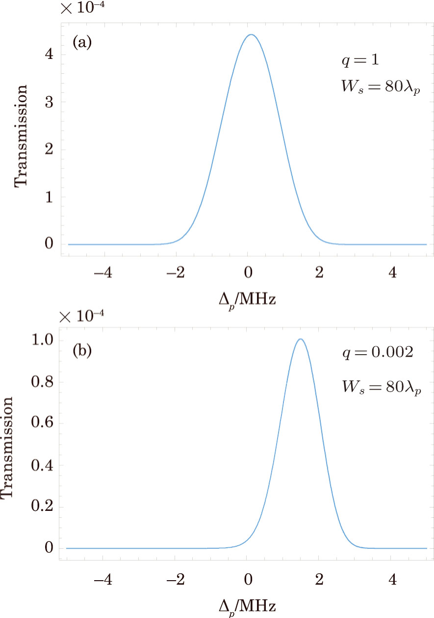
Fig. 2. (Color online) The transmission versus probe field detuning , the parameters are , , , , m = 2, and .

The beam width of PCL also plays an important role when a probe field is propagating through a medium.[3941] In these investigations,[3941] large magnitude of the GHS and intensity of diffraction grating have been revealed for small beam width and vice versa. Therefore, here we are interested to investigate the influence of beam width on the transparency peak of probe light field. We choose the spatial coherence q=0.002 and investigate the transmission spectrum for different values of beam width of PCL. We plot the transmission of probe field versus probe field detuning as shown in Fig. 3. In Fig. 3(a), we show the transmission spectrum of probe field by considering the beam width of PCL . The transmission peak of probe field decreases in comparison of Fig. 2(b) where we considered q=0.002 and . This shows that by increasing the beam width of PCL field, the transmission peak decreases. For further increase of the beam width of PCL, the transmission peak decreases further as depicted in Fig. 3(b).

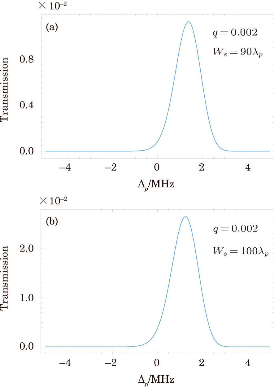
Fig. 3. (Color online) The transmission versus probe field detuning , the other parameters remain the same as in Fig. 2.

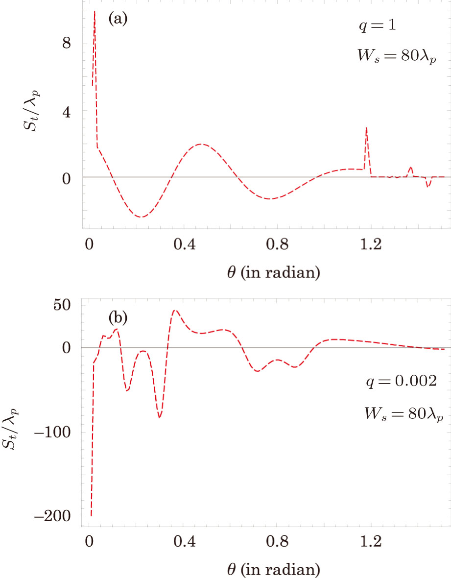
Besides, the transmission spectrum of probe field, next we study the influence of PCL field on the GHS in the TL. We use Eq. (5) and investigate the influence of spatial coherence and beam width on the amplitude of the GHS in the transmitted beam. By considering a large width of i.e., of PCL and probe field detuing , we plot the GHS in the TL versus incident angle θ for two values of spatial coherence q as shown in Fig. 4. The plot in Fig. 4(a) shows that the GHS in the TL is positive as well as negative at different incident angle θ for a coherent light i.e., q = 1. It should be noted that the transmission spectrum in Fig. 2(a) and the GHS in the TL in Fig. 4(a) are shown for coherent light field and both figures. have the same parameters. Next, we consider a PCL as used for the transmission spectrum in Fig. 2(b) and plot the GHS in the TL versus incident angle θ by considering as shown in Fig. 4(b). The plot shows that the magnitude of the GHS in the TL increases for PCL field. In comparison of Figs. 2(b) and 4(b), we conclude that for high transmission of probe field, the magnitude of the GHS in the TL increases.

Fig. 4. (Color online) The GHS versus incident angle θ for , the other parameters remain the same as in Fig. 2.

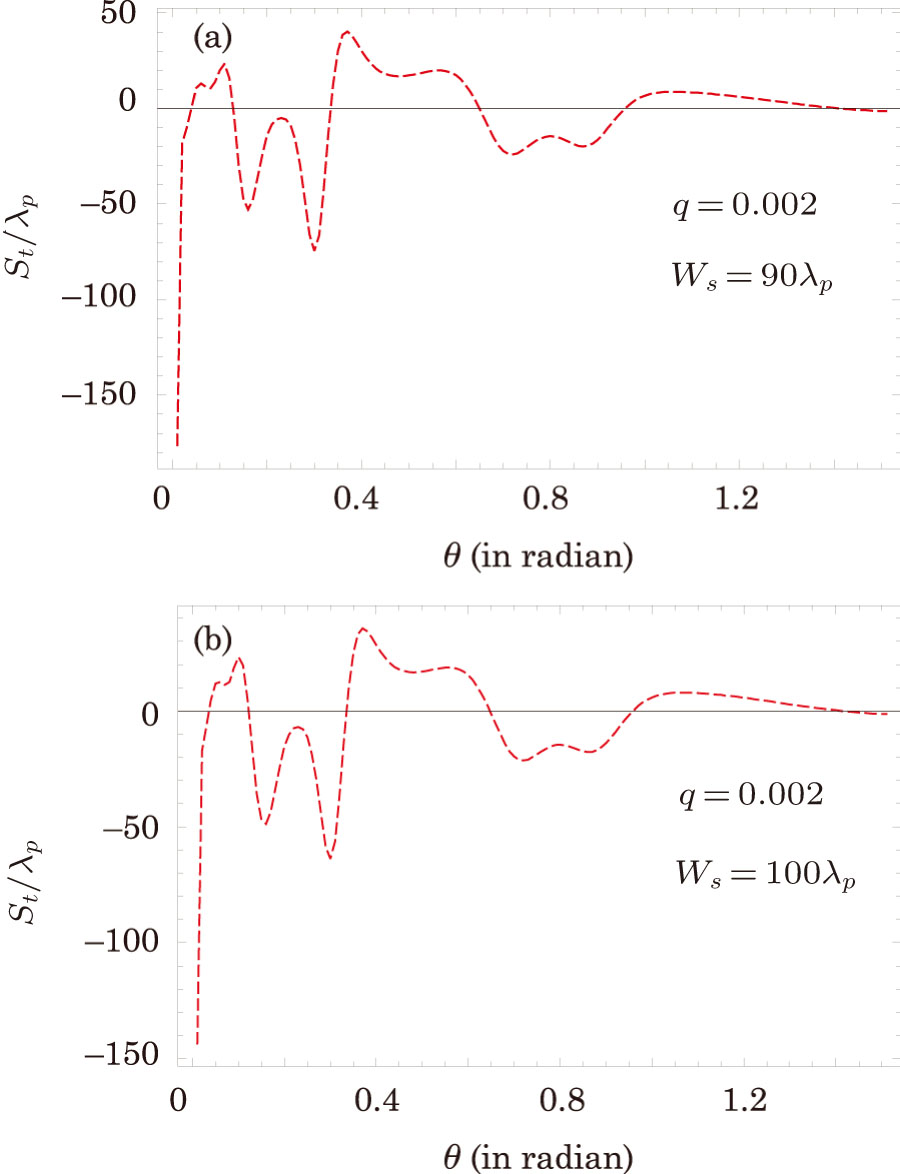
To study the influence of beam width of PCL on the GHS in the TL, we choose the spatial coherence q=0.002 and vary the beam width. In the previous section, we investigated giant negative and positive shifts in the TL by considering and q=0.002 as shown in Fig. 4(b). Now we increase the beam width from to and remain unchanged all the other parameters and plot again the GHS in the TL versus incident angle θ as depicted in Fig. 5(a). The plot shows that the magnitude of the GHS decreases with increasing the beam width of PCL. Similar reduction of transparency peak is also investigated in Fig. 3(a) for the same parameters. Similarly, for further increase of the beam width of PCL, the magnitude of the GHS decreases further as shown in Fig. 5(b).

Fig. 5. (Color online) The GHS versus incident angle θ for , the other parameters remain the same as in Fig. 2.

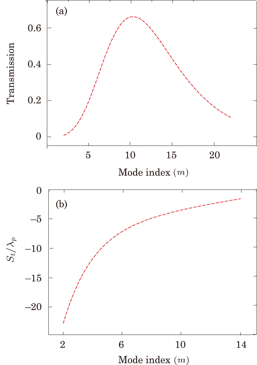
The influence of different modes on the GHS has been studied earlier,[36] in the following we study the effect of different modes of PCL on the transmission spectrum and magnitude of the GHS in the transmitted light. For incident angle θ=0 and q=0.002, we plot the transmission of probe field versus mode index m as depicted in Fig. 6(a). The plot shows that the transmission of probe field increases to its maximum value m = 10 and then decreases for further increasing the number of modes. Similarly, by considering θ=0.71 rad and q=0.002, we plot the GHS versus mode index m of PCL as shown in Fig. 6(b). The plot shows that the magnitude of the negative GHS in the transmitted becomes maximum for m = 2 and decreasing for further increasing the mode index m.

Fig. 6. (Color online) The transmission and GHS versus mode index m for , the other parameters remain the same as in Fig. 2.
4. Summary

In summary, we considered a cold atomic medium of cascade configuration having Rydberg excitation. A PCL beam is incident on a medium having length L and making an angle θ with z-axis. We studied the transmission of probe field and GHS in the TL under the influence of spatial coherence and beam width of PCL field. Maximum transmission of probe field is achieved for PCL field while low transmission for coherent light. Similarly, giant GHS in the TL is revealed for PCL field while investigated GHS with small magnitude for coherent light. The influence of beam width of PCL on the transmission spectrum and GHS in the TL is also studied. Maximum transmission of probe field and giant GHS in the TL are investigated for small beam width of PCL and vice versa.

Reference
[1] Gallagher T. Rydberg Atoms Cambridge University Press Cambridge 2005
[2] Lukin M. D. Fleischhauer M. Cote R. Phys. Rev. Lett. 87 2001 037901
[3] Gallagher T. F. Rydberg Atoms Cambridge University Press Cambridge 1994
[4] Saffman M. Walker T. G. Molmer K. Rev. Mod. Phys. 82 2010 2313
[5] Jaksch D. Cirac J. I. Zoller P. et al. Phys. Rev. Lett. 85 2000 2208
[6] Muller M. Lesanovsky I. Weimer H. et al. Phys. Rev. Lett. 102 2009 170502
[7] Weimer H. et al. Phys. Rev. Lett. 101 2008 250601
[8] Weimer H. Buchler H. P. Phys. Rev. Lett. 105 2010 230403
[9] Pohl T. Demler E. Lukin M. D. Phys. Rev. Lett. 104 2010 043002
[10] Hammerer K. Sorensen A. S. Polzik E. S. Rev. Mod. Phys. 82 2010 1041
[11] Nielsen A. E. B. Molmer K. Phys. Rev. A 81 2010 043822
[12] Petrosyan D. Fleischhauer M. Phys. Rev. Lett. 100 2008 170501
[13] Lukin M. D. et al. Phys. Rev. Lett. 87 2001 037901
[14] Vogt T. et al. Phys. Rev. Lett. 97 2006 083003
[15] Honer J. Low R. Weimer H. et al. Phys. Rev. Lett. 107 2011 093601
[16] Miller J. L. Phys. Today 65 2012 14
[17] Huang J. F. Liao J. Q. Sun C. P. Phys. Rev. A 87 2013 023822
[18] Pritchard J. D. Maxwell D. Gauguet A. et al. Phys. Rev. Lett. 105 2010 193603
[19] Petrosyan D. Otterbach J. Fleischhauer M. Phys. Rev. Lett. 107 2011 213601
[20] Shui T. Yang W. X. Zhu Z. et al. Phys. Rev. A 97 2018 033819
[21] Liu S. Yang W. X. Zhu Z. et al. Opt. Lett. 43 2018 9
[22] Goos F. Häncehn H. Ann. Phys. (Leipzig) 1 1947 333
[23] Renard R. H. J. Opt. Soc. Am. 54 1964 1190
[24] Qing D. K. Chen G. Opt. Lett. 29 2004 872
[25] Lotsch H. K. V. J. Opt. Soc. Am. 58 1968 551
[26] Tamir T. Bertoni H. L. J. Opt. Soc. Am. 61 1971 1397
[27] Chu S. Wong S. Phys. Rev. Lett. 48 1982 738
[28] Birman J. L. Pattanayak D. N. Puri A. Phys. Rev. Lett. 50 1983 1664
[29] Lakhtakia A. Electromagnetics 23 2003 71
[30] Berman P. R. Phys. Rev. E 66 2002 067603
[31] Wang L. G. Ikram M. Zubairy M. S. Phys. Rev. A 77 2008 023811
[32] Ziauddin Qamar S. Zubairy M. S. Phys. Rev. A 81 2010 023821
[33] Ziauddin Qamar S. Phys. Rev. A 84 2011 053844
[34] Ziauddin Qamar S. Phys. Rev. A 85 2012 055804
[35] Abbas M. Ziauddin Qamar S. Laser Phys. Lett. 11 2014 015201
[36] Ziauddin Chuang Y. L. Lee R. K. Phys. Rev. A 92 2015 013815
[37] Ziauddin Lee R. K. Qamar S. Opt. Commun. 379 2016 68
[38] Yang W. X. Liu S. Zhu Z. et al. Opt. Lett. 40 2015 3133
[39] Wang L. G. Zhu S. Y. Zubairy M. S. Phys. Rev. Lett. 111 2013 223901
[40] Ziauddin Chuang Y. L. Lee R. K. Phys. Rev. A 91 2015 013803
[41] Asghar S. Ziauddin Qamar S. Qamar S. JOSA B 34 2017 148
[42] Mohapatra A. K. Jackson T. R. Adams C. S. Phys. Rev. Lett. 98 2007 113003
[43] Mohapatra A. K. et al. Nature Phys. 4 2008 890
[44] Tauschinsky A. et al. Phys. Rev. A 81 2010 063411