2. 中国石油大学(华东)石油工程学院, 山东 青岛 266580
2. College of Petroleum Engineering, China University of Petroleum, Qingdao, Shandong, 266580, China
天然气水合物资源广泛分布于陆地冻土带和海洋,资源潜力巨大,是极为重要的非常规能源[1-2]。经济有效的开采方法是实现水合物资源商业化利用的关键。目前,水合物藏的开采模式主要有降压法[3]、注热法[4]、注化学剂法[5]、气体置换法[6]等。现场试验和研究显示[7-9],降压法与注热法结合是实现水合物资源开发利用最可能的方法。二者通过破坏水合物的稳定状态,使其分解为气体和水而实现水合物资源的开发利用。但单一的降压开采容易造成二次水合物和冰的形成而堵塞流动通道,仅靠注热开采也存在热损失过大的问题。
蒸汽吞吐和热水吞吐是稠油油藏开采的主要技术,在开采过程中主要包括注热、焖井和开井3个周期性环节[10-11]。对于水合物藏而言,热流体(蒸汽或热水等)吞吐法能够结合降压法和注热法两种机制,避免两种方法单独作用时的缺点,提高开发效果。与稠油油藏不同,在开采过程中,相对于热水,注入蒸汽的热损失过大,热水吞吐是水合物藏开采的可行方法[12]。同时,由于水合物的导热性能很差,在吞吐过程中,一般不考虑焖井[13]。
目前,有关热水吞吐开发水合物藏的研究不多,且已有的研究中(如Li等[14-15])过短的生产周期(如注入2 d,生产3 d)在现场不具有操作性。本文在结合实际水合物藏参数基础上,使用数值模拟方法,参照石油工业多周期吞吐的生产制度[10],分析了热水吞吐开发水合物藏的效果,并对热水吞吐过程中降压和注热的作用进行了探讨,以加强对水合物资源开发规律的认识。
1 研究方法水合物藏开采动态的预测主要通过数值模拟实现,相关的数值模拟器有CMG-STARS[16]、HydrateResSim(HRS)[17]、MH21-HYDRES[18]、STOMP-HYD[19]、TOUGH+HYDRATE[20]等。其中,HydrateResSim(HRS)是专门用于水合物藏开采模拟的开源代码。它考虑了水合物藏开采过程中的相变、传热、多相渗流等机理,能够对水合物藏开采过程中的物质和能量变化进行有效描述。许多学者使用HRS模拟器对水合物藏的开采进行了研究[21-23]。
内边界条件是井的生产控制条件,主要有定井底流压生产和定流量生产两类。而原始的HRS代码对内边界条件的处理很简单:将井眼所经过的网格处理为独立的源汇,相互之间没有影响,这对于定井底流压生产来说影响不大,但对于定流量生产则有很大影响。此外,HRS只能模拟单一生产条件下水合物藏的开采,不具有复杂生产制度下的模拟能力。
考虑到模拟研究的需要,对HRS代码进行了改进,完善了定流量条件下的控制,将各网格之间的流体流量按其流度(流体的有效渗透率与黏度之比)进行分配,同时加入了定流量和定井底流压两种边界条件的转换控制,从而能够实现热水吞吐开发水合物藏的模拟研究。具体过程为:热水吞吐过程是一个周期性的过程,每个周期包括两个阶段,即热水注入阶段和开井生产阶段。如图 1所示,在热水注入阶段,热量进入储层,热波及范围内的水合物分解为气体和水;在开井生产阶段,储层中的气体和水被采出,在此过程中造成地层压力的下降,又促进了水合物的分解。
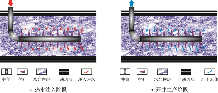 |
| 图1 热水吞吐法开采水合物藏示意图 Fig. 1 Sketch of the hydrate reservoir mining by huff-and-puff hot water injection |
当产气速率降低到一定值(即各周期产气速率的下限值)后,开始下一个周期的模拟生产。由于水合物藏的注入性较差,随着生产的进行,储层渗透性逐渐变好。因此,在生产初期先进行一段时间的降压开采,以提高水合物藏的注入能力;同时,热水吞吐生产时,将各周期的热水注入量随周期数按一定比例递增。
模拟研究时,假设水合物是单一的甲烷水合物,体系由水合物相、水相和气相组成,且3相均存在于储层孔隙中。各相的流动遵守达西定律,相对渗透率模型见式(1),毛管力模型见式(2)。
| $ \left \{ \begin{array}{l} {{K}_{\rm rw}}=\min \left[{{\left( \dfrac{{{S}_{\rm w}}-{{S}_{\rm irw}}}{1-{{S}_{\rm irw}}} \right)}^{{{n}_{\rm w}}}}, 1 \right] \\[7pt] {{K}_{\rm rg}}=\min \left[{{\left( \dfrac{{{S}_{\rm g}}-{{S}_{\rm irg}}}{1-{{S}_{\rm irw}}} \right)}^{{{n}_{\rm g}}}}, 1 \right] \\ {{K}_{\rm rh}}=0 \end{array} \right . $ | (1) |
式中:
| $ {{p}_{{\rm c}}}=-{{p}_{{\rm c0}}}{{\left[{{\left( \dfrac{{{S}_{\rm w}}-{{S}_{\rm irw}}}{1-{{S}_{\rm irw}}} \right)}^{-1/\lambda }}-1 \right]}^{1-\lambda }} $ | (2) |
式中:
研究区块位于中国南海北部陆坡中段神狐海域,具备良好的水合物成藏地质条件和适宜的温压环境。取芯研究发现[24-25]:该海域水合物层厚10~25 m,水合物饱和度20%~48%,资源潜力巨大。
2.2 模型建立基于SH7取芯点的水合物藏参数,建立水平井热水吞吐开采水合物藏的三维数值模型(图 2)。
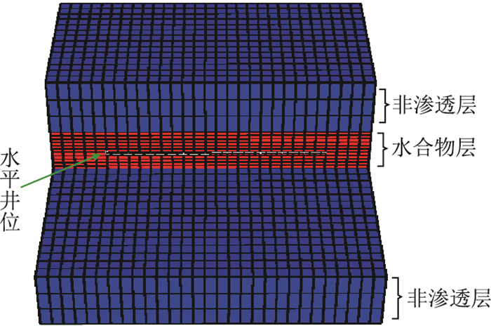 |
| 图2 水合物藏开采数值模拟模型 Fig. 2 Numerical model of the hydrate reservoir mining |
模型由顶部非渗透层、水合物层和底部非渗透层组成。模型大小为290 m×290 m×82 m,对应的网格大小为%
| 表1 模型水合物层基础参数 Tab. 1 Model parameters of the hydrate-bearing layer |
| 表2 模型生产参数 Tab. 2 Operation parameters of the model |
截至模拟结束,共进行了4个周期的生产。模型产气速率及累计产气量、分解气速率及累计分解气量的变化曲线分别如图 3和图 4所示。产气速率呈现明显的周期性变化,各周期内产气速率整体呈先增加后降低的趋势;随周期数增加,各周期的生产时间逐渐变长,由第1周期的不足5 d延长到第4周期的超过180 d,表明开发效果逐渐变好。
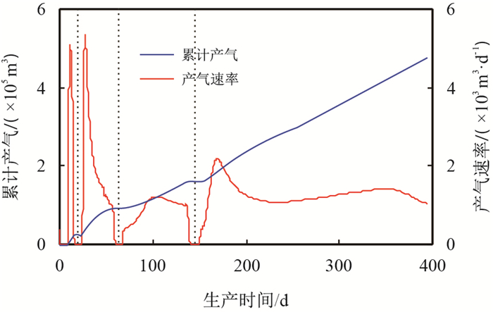 |
| 图3 产气速率和累计产气量曲线 Fig. 3 Curve of the gas production rate and the cumulative gas production |
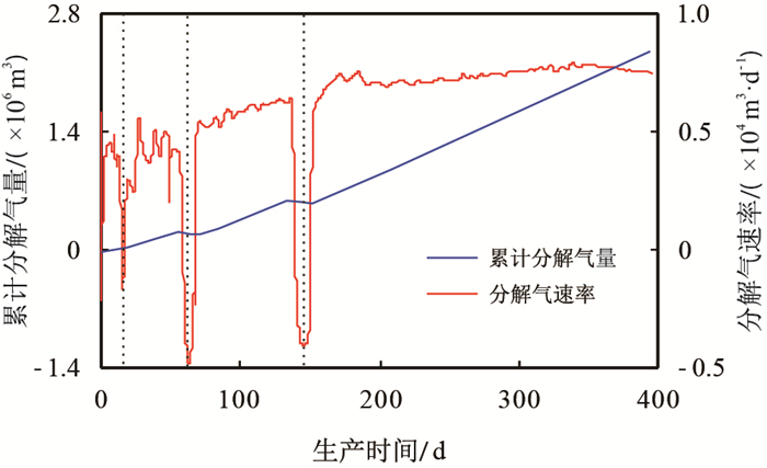 |
| 图4 分解气速率和累计分解气量曲线 Fig. 4 Curve of the gas decomposition rate and the cumulative gas decomposition |
整个生产期内,分解气速率的变化规律较为复杂,各周期内的分解速率存在一定程度的波动。在热水注入阶段,分解气的速率为负值,意味着有水合物的生成,这主要是由于在热水注入阶段,井底的温压条件有利于气体和水生成水合物。在开井生产阶段,分解气速率随着周期数增加,整体呈上升趋势,平均分解气速率由第1周期的3 800 m3/d上升到7 400 m3/d,增幅达95%,表明水合物分解效果越来越好。这是由于随着生产的进行,热水注入量逐渐增加,且生产阶段导致的地层压力下降明显,促使储层中水合物持续分解。
随生产时间的增加,累计产气量和累计分解气量近似呈线性增长。生产结束时,约有80%的分解气体滞留在储层未被采出(累计分解气量为2.36×10⁶ m3、累计产气量为4.75×10⁵ m3),采出比例较低,需要采取相关措施提高分解气的采出比例。
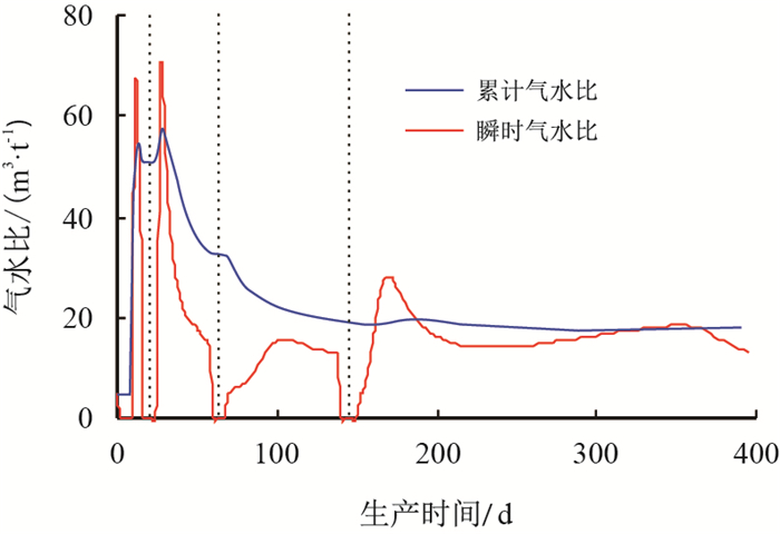
图 5为瞬时气水比和累计气水比的变化曲线(瞬时气水比为产气速率与产水速率的比值;累计气水比为累计产气与累计产水的比值)。瞬时气水比的变化与产气速率类似,产水速率较为稳定,气水比的变化主要受产气速率的影响。累计气水比在生产初期快速下降,然后趋于20 m3/t的水平。这主要是由于产水速率较为稳定,开始阶段产气速率较高,累计气水比增长很快,而生产后期产气速率大致平稳,累计气水比变化较小。
 |
| 图5 气水比曲线 Fig. 5 Curve of the gas-water ratio |
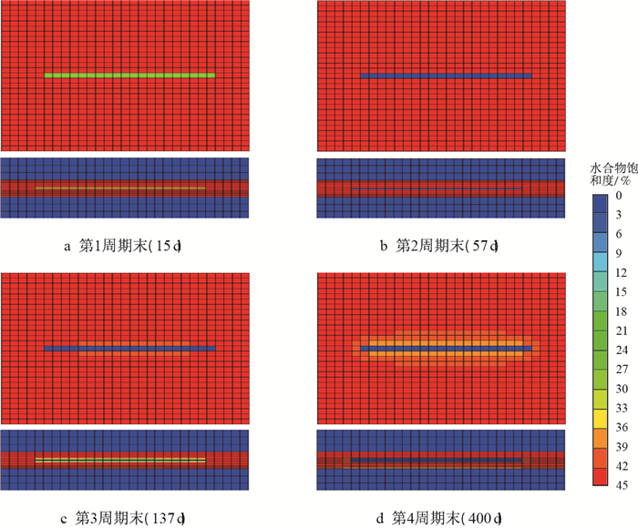
水合物饱和度的变化能定量反映水合物的分解情况。图 6为各周期末水平井周围的水合物饱和度分布情况(通过水平井的水平和垂直剖面)。随生产时间的增加,水合物以水平井为中心不断分解。从第1周期至第2周期,水合物的分解主要局限在井筒所在网格,而从第3周期开始,分解范围扩展明显,低水合物饱和度区域在水平和垂向上均不断扩大。同时可以看出,模拟结束时,井筒附近(半径约6~10 m)的水合物已经完全分解,且距离井筒越远,水合物的分解程度越低。因此,热水吞吐能够有效促进水合物的分解,但受效范围主要局限在近井区域,远井区域的水合物动用程度很低。
 |
| 图6 各周期末模型水合物饱和度场 Fig. 6 The gas hydrate saturation field at the end of each cycle |
截至生产结束,水合物层平均水合物饱和度降至0.420,水合物的分解程度(已分解的水合物质量与初始水合物质量之比)约为4%。调整生产参数,如增加生产时间、优化生产参数等,能获得更高的水合物分解程度。
3.2 开发效果对比热水吞吐开发模拟结束后,水合物层平均压力降至12 MPa,累计注入80 ℃的热水约2 000 t。在热水吞吐过程中,降压和注热作用共同促进了水合物的分解,为对比二者的单独作用效果,分别建立了两种开采模型。
在模型1中,仅使用降压法开采水合物藏:保持井底压力为8.3 MPa进行模拟开采,生产400 d。模拟结束时水合物层的平均压力降至12 MPa(同基础模型)。其他参数条件与基础模型相同。
在模型2中,仅使用注热法开采水合物藏:以恒定功率16.4 kW对水平井进行井底加热,生产400 d。其中,加热功率的确定如式(3)所示,模型2中加热储层的能量与基础模型相同。
| $ h={{{Q}_{\rm inj}}}/{t} $ | (3) |
式中:
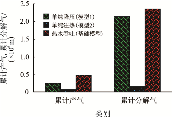
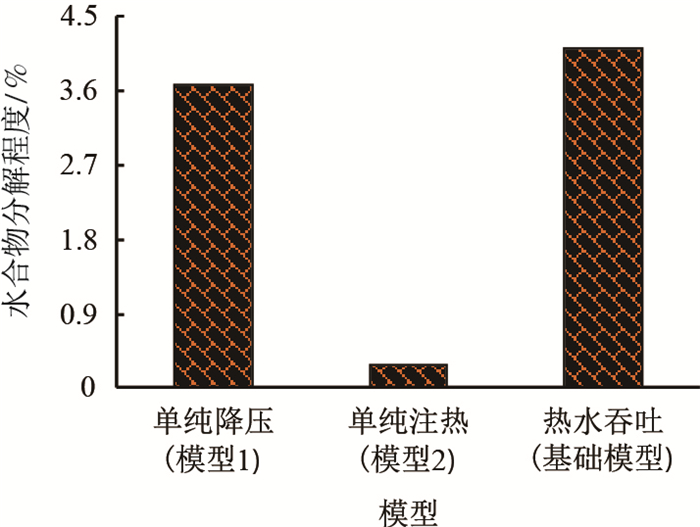
生产结束时,不同模型的累计产气量及累计分解气量、水合物分解程度分别如图 7、图 8所示。
 |
| 图7 不同模型的累计产气和累计分解气 Fig. 7 Cumulative gas production and cumulative gas decomposition in different models |
 |
| 图8 不同模型的水合物分解程度 Fig. 8 Gas hydrate decomposition degree in different models |
截至模拟结束,仅采用降压开采或仅采用注热开采得到的累计产气量、累计分解气量和水合物分解程度均低于热水吞吐开采条件下的值,且二者之和也低于热水吞吐的情况(累计产气:2.57×10⁵+7.94×10⁴ < 4.75×10⁵;累计分解气:2.15×10⁶+1.69×10⁵ < 2.36×10⁶;水合物分解程度:3.67%+0.29% < 4.11%)。这表明,相对于单纯的降压开采或注热开采,热水吞吐具有更好的水合物藏开发效果,可以获得更高的产气量、分解气量和水合物分解程度;同时,能够发挥降压和注热两者的作用,具有一定的协同效应。此外,从生产指标上可以看出,单纯降压开采的效果次之,而单纯注热开采的效果最差。
4 结论(1) 热水吞吐开采水合物藏时,产气速率呈周期性变化,随周期数增加,周期生产时间逐渐变长,分解气速率呈上升趋势,开发效果逐渐变好。模拟结束时,仅有20%的分解气采出至地表,采出比例较低。因此,热水吞吐开发水合物藏时应采取合适措施提高分解气的采出比例。
(2) 热水吞吐开采水合物藏时,水合物的分解以水平井筒为中心逐渐向外扩展,受效范围主要在井筒附近,近井地带水合物分解程度高,距离井筒越远,水合物分解程度越低。
(3) 热水吞吐兼具降压作用和注热作用,且存在一定的协同效应,其开发效果好于二者单独作用时的情况,能够获得更高的产气量、分解气量和水合物分解程度。
| [1] |
BAYLES GA, SAWYER WK, ANADA HR, et al. A steam cycling model for gas production from a hydrate reservoir[J]. Chemical Engineering Communications, 2007, 47(4-6): 225-245. |
| [2] |
王屹, 李小森. 天然气水合物开采技术研究进展[J]. 新能源进展, 2013, 1(1): 69-79. WANG Yi, LI Xiaosen. Research progress of natural gas hydrate production technology[J]. Advances in New and Renewable Energy, 2013, 1(1): 69-79. doi: 10.3969/j.issn.2095-560X.2013.01.007 |
| [3] |
HOLDER G D, ANGERT P F. Simulation of gas production from a reservoir containing both gas hydrates and free natural gas[C]. SPE Annual Technical Conference and Exhibition, New Orleans, Louisiana, 1982.
|
| [4] |
MCGUIRE P L. Methane hydrate gas production by thermal stimulation[C]. The Fourth Canadian Permafrost Conference, Calgary, Alberta, Canada, 1981.
|
| [5] |
KAMATH V A, GODBOLE S P. Evaluation of hot-brine stimulation technique for gas production from natural gas hydrates[J]. Journal of Petroleum Technology, 1987, 39(11): 1379-1388. doi: 10.2118/13596-PA |
| [6] |
OHGAKI K, TAKANO K, SANGAWA H, et al. Methane exploitation by carbon dioxide from gas hydrates-phase equilibria for CO2-CH4 mixed hydrate system[J]. Journal of Chemical Engineering of Japan, 1996, 29(3): 478-483. doi: 10.1252/jcej.29.478 |
| [7] |
SLOAN E D, KOH C. Clathrate hydrates of natural gases[M]. 3th Edition. CRC Press, 2007.
|
| [8] |
SUN Youhong, LI Bing, GUO Wei, et al. Comparative analysis of the production trial and numerical simulations of gas production from multilayer hydrate deposits in the Qilian Mountain permafrost[J]. Journal of Natural Gas Science & Engineering, 2014, 21(2): 456-466. doi: 10.1016/j.jngse.2014.09.005 |
| [9] |
LI Xiaosen, XU Chungang, ZHANG Yu, et al. Investigation into gas production from natural gas hydrate:A review[J]. Applied Energy, 2016, 172: 286-322. doi: 10.1016/j.apenergy.2016.03.101 |
| [10] |
SCOTT G R. Comparison of CSS and SAGD performance in the Clearwater Formation at Cold Lake[C]. SPE International Thermal Operations and Heavy Oil Symposium and International Horizontal Well Technology Conference, Calgary, Alberta, Canada, 2002.
|
| [11] |
朱国金, 余华杰, 郑伟, 等. 海上稠油多元热流体吞吐开发效果评价初探[J]. 西南石油大学学报(自然科学版), 2016, 38(4): 89-94. ZHU Guojin, YU Huajie, ZHENG Wei, et al. Thermal recovery effect evaluation of multi-thermal fluid stimulation in offshore heavy oilfield[J]. Journal of Southwest Petroleum University (Science & Technology Edition), 2016, 38(4): 89-94. doi: 10.11885/j.issn.1674-5086.2014.03.28.02 |
| [12] |
MORIDIS G J. Numerical studies of gas production from class 2 and class 3 hydrate accumulations at the Mallik Site, Mackenzie Delta, Canada[J]. SPE Reservoir Evaluation & Engineering, 2004, 7: 175-183. doi: 10.2118/88039-PA |
| [13] |
李刚, 李小森. 单井热吞吐开采南海神狐海域天然气水合物数值模拟[J]. 化工学报, 2011, 62(2): 458-468. LI Gang, LI Xiaosen. Numerical simulation for gas production from hydrate accumulated in Shenhu Area, South China Sea, using huff and puff method[J]. CIESC Journal, 2011, 62(2): 458-468. |
| [14] |
LI G, MORIDIS G J, ZHANG K, et al. The use of huff and puff method in a single horizontal well in gas production from marine gas hydrate deposits in the Shenhu Area of South China Sea[J]. Journal of Petroleum Science and Engineering, 2011, 77(1): 49-68. doi: 10.1016/j.petrol.2011.02.009 |
| [15] |
SU Z, MORIDIS G J, ZHANG K, et al. A huff-and-puff production of gas hydrate deposits in Shenhu area of South China Sea through a vertical well[J]. Journal of Petroleum Science & Engineering, 2012, 86-87(3): 54-61. doi: 10.1016/j.petrol.2012.03.020 |
| [16] |
CMG STARS. Advanced process and thermal reservoir simulator[M]. Canada: Computer Modelling Group Ltd., 2015.
|
| [17] |
MORIDIS G J, KOWALSKY M B, PRUESS K. HydrateRessim user's manual:A numerical simulator for modeling the behavior of hydrates in geologic media[M]. USA: Lawrence Berkeley National Laboratory, 2005.
|
| [18] |
KURIHARA M, OUCHI H, MASUDA Y, et al. Assessment of gas productivity of natural methane hydrates using MH21 Reservoir simulator[C]. Proceedings of the AAPG Hedberg Conference, Canada, 2004.
|
| [19] |
WHITE M D, OOSTROM M. STOMP:Subsurface transport over multiple phases[M]. USA: Pacific Northwest National Laboratory, 2006.
|
| [20] |
MORIDIS G J, KOWALSKY M B, PRUESS K. TOUGH+HYDRATE v1.2 user's manual:A code for the simulation of system behavior in hydrate-bearing geologic media[M]. USA: Lawrence Berkeley National Laboratory, 2012.
|
| [21] |
GAMWO I K, LIU Y. Mathematical modeling and numerical simulation of methane production in a hydrate reservoir[J]. Industrial & engineering chemistry research, 2010, 49(11): 5231-5245. doi: 10.1021/ie901452v |
| [22] |
樊栓狮, 杨圣文, 温永刚, 等. 水平井高效开采Class 3天然气水合物研究[J]. 天然气工业, 2013, 33(7): 36-42. FAN Shuanshi, YANG Shengwen, WEN Yonggang, et al. A simulation study of Class Ⅲ hydrate production with a high efficiency through the depressurization recovery and thermal stimulation in horizontal wells[J]. Natural Gas Industry, 2013, 33(7): 36-42. doi: 10.3787/j.issn.1000-0976.2013.07.006 |
| [23] |
MEREY S, SINAYUC C. Numerical simulations for shortterm depressurization production test of two gas hydrate sections in the Black Sea[J]. Journal of Natural Gas Science and Engineering, 2017, 44: 77-95. doi: 10.1016/j.jngse.2017.04.011 |
| [24] |
WU Nengyou, YANG Shengxiong, ZHANG Haiqi, et al. Gas hydrate system of Shenhu Area, Northern South China Sea: Wire-line logging, geochemical results and preliminary resources estimates[C]. Offshore Technology Conference, 2010.
|
| [25] |
张伟, 梁金强, 何家雄, 等. 南海北部神狐海域GMGSl和GMGS3钻探区天然气水合物运聚成藏的差异性[J]. 天然气工业, 2018, 38(3): 138-149. ZHANG Wei, LIANG Jinqiang, HE Jiaxiong, et al. Differences in natural gas hydrate migration and accumulation between GMGS1 and GMGS3 drilling areas in the Shenhu Area, northern South China Sea[J]. Natural Gas Industry, 2018, 38(3): 138-149. doi: 10.3787/j.issn.10000976.2018.03.017 |
| [26] |
MORIDIS G J, KOWALSKY M B, PRUESS K. Depressurization-induced gas production from class-1 hydrate deposits[J]. SPE Reservoir Evaluation & Engineering, 2007, 10(5): 458-481. doi: 10.2118/97266-PA |
| [27] |
MORIDIS G J, REAGAN M T, KIM S J, et al. Evaluation of the gas production potential of marine hydrate deposits in the Ulleung Basin of the Korean East Sea[J]. SPE110859-PA, 2009. doi: 10.2118/110859-PA |
 2018, Vol. 40


