2. The University of Oklahoma, USA, 660 Parrington Oval, Norman, OK 73019-0390;
3. 中国石油天然气股份有限公司北京油气调控中心, 北京 朝阳 100007;
4. 中国石化石油勘探开发研究院, 北京 海淀 100086
2. The University of Oklahoma, 660 Parrington Oval, Norman, OK 73019-0390, USA;
3. PetroChina Beijing Oil & Gas Pipeline Control Center, Chaoyang, Beijing 100007, China;
4. Exploration & Production Research Institute, SINOPEC, Haidian, Beijing 100086, China
国内外多年生产实践表明,对于特稠油及超稠油油藏, 常规开采方法开发效果较差,而SAGD是一项开采特稠油及超稠油油藏较成功的技术[1-5]。目前国内外针对SAGD产能做了很多深入的研究,1981年Butler提出蒸汽辅助重力泄油产能预测模型[6-13],但是后来很多人对该模型的泄油机理提出了质疑:Adegbesan[14]于1991年通过分析SAGD矿场试验数据得出:SAGD开采前期主要靠注采井间压差驱替稠油,然后才是重力泄油逐渐占主导作用;Edmunds[15]于1993年提出Subcool概念,认为因汽液界面产生的注采压差对生产起着重要作用;Suzuki[16]于1996年指出SAGD开采过程中还存在压差驱替作用;Farouq AIi[17]于1997年对SAGD开采过程的重力泄油机理提出质疑,他指出在开采过程中,不仅仅存在重力驱替机理,并且SAGD开采机理比Butler想象的更加复杂;陈元千[18]于2015年对Butler产能公式提出质疑,认为注采压差对SAGD泄油起着不可忽略的作用。虽然他们都认为SAGD开采过程中注采压差对SAGD开采起着重要作用,但是也只是提出了SAGD生产过程压差驱替这一普遍现象,而没给出考虑注采压差情况下的产能预测公式。
因此,本文在基于Butler产能预测模型[7]的基础上,考虑注采压差对SAGD生产的影响,推导出了考虑注采压差作用的产能预测模型,分析了注采压差对SAGD开发效果的影响,并结合现场数据进行了产能预测。
1 数学模型的建立 1.1 基本假设数学模型基本假设:(1)蒸汽冷凝形成的水相进入油相,形成的混合物与油相具有相同的性质;(2)忽略高温作用下,油水裂解反应产生的影响;(3)蒸汽腔内部等温等压;(4)SAGD沿程均匀吸汽,任意剖面产量及产油速度相等;(5)流体渗流满足达西定律;(6)注采压差未达到汽窜临界值。
1.2 斜面泄油速率方程这里将蒸汽腔简化为一个倒三角形[19],其一侧的形状如图 1所示。
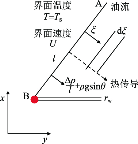 |
| 图1 蒸汽-油藏交接面垂直剖面 Fig. 1 Small vertical profile of steam -reservoir transfer surface |
根据达西定律,在Butler模型[7]下,单位长度水平井的流量为
| ${\rm{d}}q_{\rm{L}} = \dfrac{{\Delta \rho {\rm{g}}K\sin \theta A}}{{\mu _{\rm{o}} }} = \dfrac{{(\rho _{\rm{o}} - \rho _{\rm{g}} ){\rm{g}}K\sin \theta }}{{\mu _{\rm{o}} }}{\rm{d}}\xi$ | (1) |
式中:
g—重力加速度,g=9.8 m/s2;
考虑注采压差下,单位水平井长度的流量为
| ${\rm{d}}q_{\rm{L}} = \dfrac{{KA}}{{\mu _{\rm{o}} l}}\Delta p + \dfrac{{\Delta \rho {\rm{g}}K\sin \theta A}}{{\mu _{\rm{o}} }} = \left[{\dfrac{{K\sin \theta }}{{\mu _{\rm{o}} y}}\Delta p + \dfrac{{(\rho _{\rm{o}}-\rho _{\rm{g}} ){\rm{g}}K\sin \theta }}{{\mu _{\rm{o}} }}} \right]{\rm{d}}\xi$ | (2) |
式中:
势能梯度为
| ${\rm{d}}q_{\rm{L}} = \left( {\dfrac{{\Delta p}}{{\rho _{\rm{o}} y}} + {\rm{g}}} \right)\dfrac{{K\sin \theta }}{{\upsilon _{\rm{s}} }}{\rm{d}}\xi$ | (3) |
式中:
设热传递只有传导方式,那么在稳定的情况下,界面之前的温度方程为[6]
| $\dfrac{{T - T_{\rm{R}} }}{{T_{\rm{S}} - T_{\rm{R}} }} = {\rm{e}}^{ - U\xi /\alpha }$ | (4) |
式中:
其中,界面移动速度与时间的关系为
| $U = \left( {\dfrac{{\partial x}}{{\partial t}}} \right)_y \sin \theta$ | (5) |
油藏未加热区的微分流量为
| ${\rm{d}}q_{\rm{R}} = \left( {\dfrac{{\Delta p}}{{\rho _{\rm{o}} y}} + {\rm{g}}} \right)\dfrac{{K\sin \theta }}{{\upsilon _{\rm{R}} }}{\rm{d}}\xi$ | (6) |
式中:
结合式(3)和式(6),可以得到由于加热而增加的流量
| ${\rm{d}}q_{\rm{L}} - {\rm{d}}q_{\rm{R}} = K\sin \theta \left( {\dfrac{{\Delta p}}{{\rho _{\rm{o}} y}} + {\rm{g}}} \right)\left( {\dfrac{1}{{\upsilon _{_{\rm{S}} } }} - \dfrac{1}{{\upsilon _{\rm{R}} }}} \right){\rm{d}}\xi$ | (7) |
用
| $q = K\sin \theta \left( {\dfrac{{\Delta p}}{{\rho _{\rm{o}} y}} + {\rm{g}}} \right)\int\limits_0^\infty {\left( {\dfrac{1}{{\upsilon _{_{\rm{S}} } }} - \dfrac{1}{{\upsilon _{\rm{R}} }}} \right){\rm{d}}\xi }$ | (8) |
利用黏度随温度变化的经验关系式[6],该经验关系式取决于油藏内特定的石油性质,当
| $\dfrac{{\upsilon _{\rm{s}} }}{\upsilon } = \left( {\dfrac{{T - T_{\rm{R}} }}{{T_{\rm{S}} - T_{\rm{R}} }}} \right)^m$ | (9) |
式中:
利用式(4)和式(9)积分
| $\begin{array}{l} \int\limits_0^\infty {\left( {\frac{1}{\upsilon } - \frac{1}{{{\upsilon _{\rm{R}}}}}} \right)} {\rm{d}}\xi = \int\limits_{{T_{\rm{R}}}}^{{T_{\rm{S}}}} {\left[ {\frac{1}{{{\upsilon _{\rm{s}}}}}{{\left( {\frac{{T - {T_{\rm{R}}}}}{{{T_{\rm{S}}} - {T_{\rm{R}}}}}} \right)}^m} - \frac{1}{{{\upsilon _{\rm{R}}}}}} \right]} \frac{\alpha }{U}\frac{{{\rm{d}}T}}{{T - {T_{\rm{R}}}}} = \\ \quad \quad \quad \frac{\alpha }{U}\frac{1}{{m{\upsilon _{\rm{s}}}}}{\rm{ = }}\frac{\alpha }{{\frac{{ialx}}{{\partial t}}\sin \theta }}\frac{1}{{m{\upsilon _{\rm{s}}}}} \end{array}$ | (10) |
将式(10)和式(8)消去积分式,得到
| $q = \left( {\dfrac{{\Delta p}}{{\rho _{\rm{o}} y}} + {\rm{g}}} \right)K\dfrac{\alpha }{{\dfrac{{\partial x}}{{\partial t}}m\upsilon _{\rm{s}} }}$ | (11) |
物质平衡方程为
| $\left( {\dfrac{{\partial x}}{{\partial t}}} \right)_y = \dfrac{1}{{\phi \Delta S_{\rm{o}} }}\left( {\dfrac{{\partial q}}{{\partial y}}} \right)_{\rm{t}}$ | (12) |
式中:
联合式(11),式(12)得
| $q = \left( {\dfrac{{\Delta p}}{{\rho y}} + {\rm{g}}} \right)\dfrac{{K\phi \alpha \Delta S_{\rm{o}} }}{{m\upsilon _{\rm{s}} }}\left( {\dfrac{{\partial y}}{{\partial q}}} \right)_{\rm{t}}$ | (13) |
分离变量并积分得
| $\int_0^q {q{\rm{d}}q} = \int_{r_{\rm{w}} }^y {\left( {\dfrac{{\Delta p}}{{\rho y}} + {\rm{g}}} \right)\dfrac{{K\phi \alpha \Delta S_{\rm{o}} }}{{m\upsilon _{\rm{s}} }}{\rm{d}}y}$ | (14) |
式中:
对式(14)进行积分,得到水平井一侧泄油量计算式
| $q = \sqrt {\dfrac{{2K\phi \alpha \Delta S_{\rm{o}} }}{{m\upsilon _{\rm{s}} }}\left[{\dfrac{{\Delta p}}{{\rho _{\rm{o}} }}\ln \dfrac{y}{{r_{\rm{w}} }} + {\rm{g}}(y-r_{\rm{w}} )} \right]}$ | (15) |
由于只有部分压头
| $q{\rm{ = }}\sqrt {\dfrac{{\beta K\phi \alpha \Delta S_{\rm{o}} }}{{m\mu _{\rm{o}} }}\left( {\Delta p\ln \dfrac{y}{{r_{\rm{w}} }} + \rho _{\rm{o}} {\rm{g}}y} \right)}$ | (16) |
式中:
公式(16)即为考虑压差驱替下单位长度水平井泄油速率。
通常SAGD生产分为上产,稳产及衰竭3个阶段[3],其分别对应于蒸汽腔上升阶段,蒸汽腔横向扩展阶段及蒸汽腔下降阶段。图 2和图 3为SAGD生产过程中的前两个阶段,即蒸汽腔上升阶段和蒸汽腔横向扩展阶段,图中红色区域为蒸汽腔波及区域。由图 2和图 3可以看出:在上升阶段,蒸汽腔未波及到生产井,而横向扩展阶段,蒸汽腔开始波及到生产井,因此相比于上升阶段,注采井间压差变小,该物理现象证明了Adegbesan的观点[15],即:在SAGD开采前期,压差驱替占主要作用,后期重力作用逐渐起主导作用。
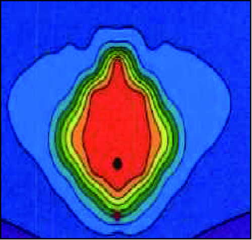 |
| 图2 蒸汽腔上升阶段 Fig. 2 The rising steam chamber |
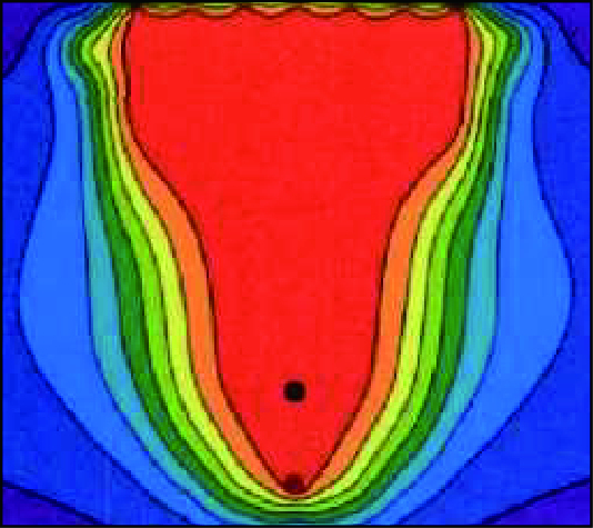 |
| 图3 蒸汽腔到达油层顶部 Fig. 3 Lateral expansion chamber |
假设蒸汽腔在上升过程中保持形状相似,因此,单位长度水平井累计产油量为
| $q_{{\rm{cum}}} = \int_0^t {q{\rm{d}}t} = \gamma \phi \Delta S_{\rm{o}} y^2$ | (17) |
式中:
对时间求微分,得到采油速度的另一表达式
| $q = 2\gamma \phi \Delta S_{\rm{o}}y\dfrac{{{\rm{d}}y}}{{{\rm{d}}t}}$ | (18) |
令方程(16)的右边×2等于方程(18)的右边,并且对该方程积分,即可以得到蒸汽腔高度
| $\gamma \phi \Delta S_{\rm{o}} y\dfrac{{{\rm{d}}y}}{{{\rm{d}}t}}\sqrt {\dfrac{{\beta K\phi \alpha \Delta S_{\rm{o}} }}{{m\upsilon _{\rm{s}} }}\left( {\dfrac{{\Delta p}}{{\rho _{\rm{o}} }}\ln \dfrac{y}{{r_{\rm{w}} }} + {\rm{g}}y} \right)}$ | (19) |
令:
| $\int {} _{{r_{\rm{w}}}}^h\frac{{Ay}}{{{\rm{C}}\sqrt {B\ln \frac{y}{{{r_{\rm{w}}}}} + {\rm{g}}y} }}{\rm{d}}y = \int_0^t {{\rm{d}}t} $ | (20) |
由于积分方程(20)没有解析解,因此,利用MATLAB求数值解,对方程右边采用迭代的方法,可以得到时间
因假设双水平井SAGD沿程均匀吸汽,故可以只研究单位长度水平井累计产油量及产油速度。以加拿大Mackay River和Dover区块的SAGD先导试验区为例,以单个双水平井井组地质参数为基础,利用热采模拟建立网格数为3×45×40的双水平井SAGD模型,每个网格长度为1 m×1 m×1 m,工作制度定为最大注汽井压力和最小生产井压力,用来稳定注采压差,如图 4所示,其中黑色区域为加密网格。模型中没有底水及气顶的存在,注汽井位于生产井上面5 m,油藏初始温度和压力分别为2350 kPa和25.7 ℃,初始含油饱和度为0.83,初始含水饱和度为0.17,油层渗透率1 800 D,地层孔隙度为0.36,黏温指数为3,热扩散系数为0.04 m2/d,原油密度为0.98 g/cm3,生产井半径为0.05 m。表 1为产能预测模型输入参数值。
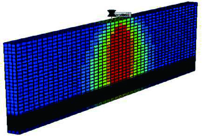 |
| 图4 三维热采模型 Fig. 4 Schematic diagram of 3D model |
| 表1 产量预测所用参数值 Table 1 The parameters of model |
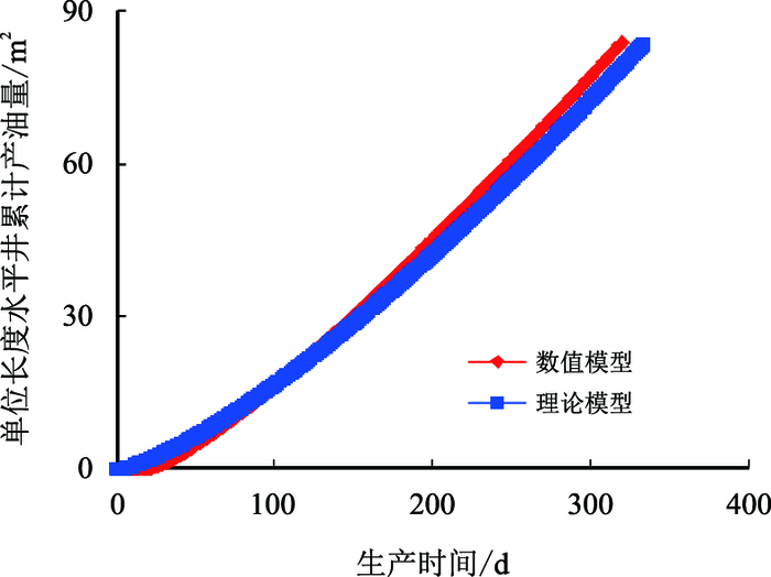
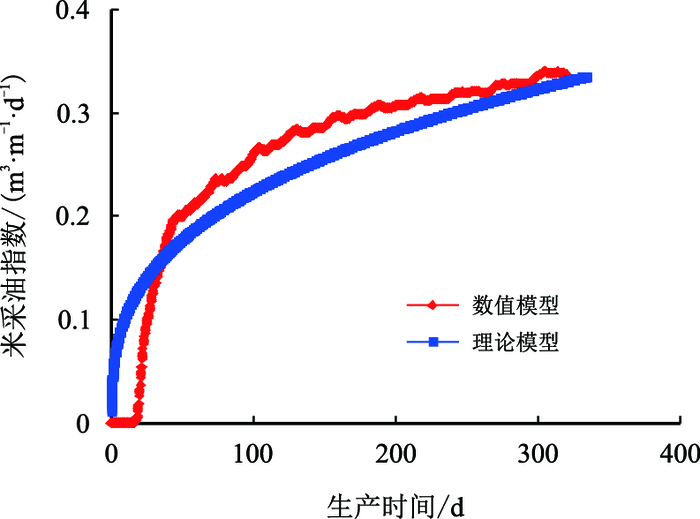
结合计算式(16),式(17),式(20),当
 |
|
图5
单位长度水平井累计产油量与时间关系( |
 |
|
图6
单位长度水平井产油速度与时间关系( |
从图 5和图 6中可以得出该数模模拟结果与Butler产能预测模型拟合效果较好。说明在不考虑压差的情况下,Butler的产能预测模型能够较好地预测产能。但是,正如前面所说,双水平井SAGD生产过程中注采压差的存在对产能的影响较大,所以如果仍然用Butler的模型去预测产能,其误差将会很大。
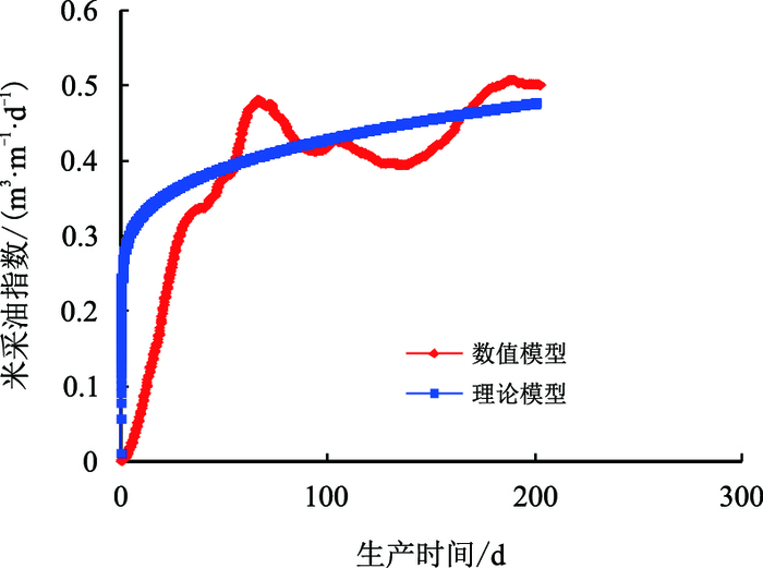
3.2 考虑压差驱替的预测结果及分析当
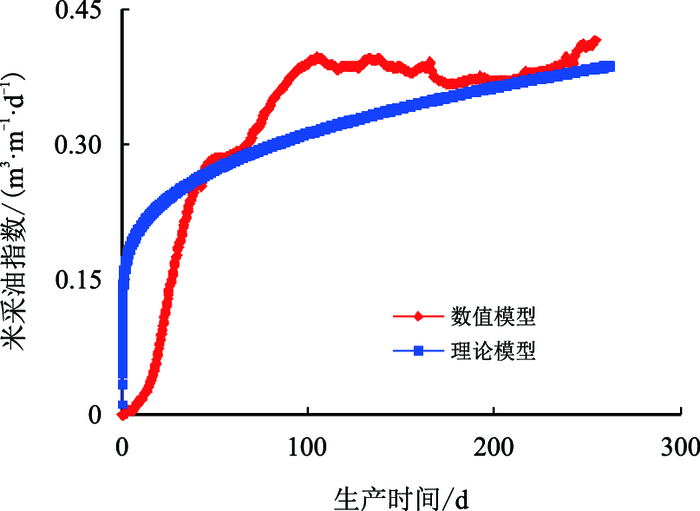 |
| 图7 注采压差20 kPa时米采油指数与时间关系 Fig. 7 The relationship between oil production rate per unit length and time when pressure difference is 20 kPa |
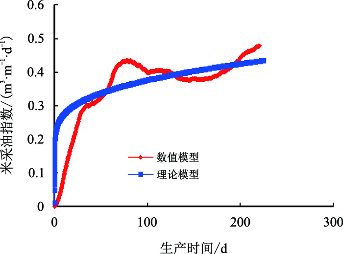 |
| 图8 注采压差40 kPa时米采油指数与时间关系 Fig. 8 The relationship between oil production rate per unit length and time when pressure difference is 40 kPa |
 |
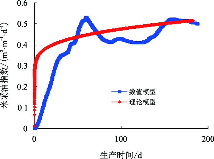
| 图9 注采压差60 kPa时米采油指数与时间关系 Fig. 9 The relationship between oil production rate per unit length and time when pressure difference is 60 kPa |
 |
| 图10 注采压差80 kPa时米采油指数与时间关系 Fig. 10 The relationship between oil production rate per unit length and time when pressure difference is 80 kPa |
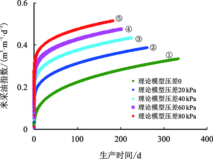 |
| 图11 不同压差下米采油指数与时间关系 Fig. 11 The relationship between oil production rate per unit length and time on different injector-producepressure difference |
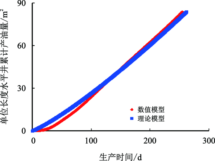 |
| 图12 注采压差20 kPa时累计产油量与时间关系 Fig. 12 The relationship between cumulative oil production per unit length and time when pressure difference is 20 kPa |
 |
| 图13 注采压差40 kPa时累计产油量与时间关系 Fig. 13 The relationship between cumulative oil production per unit length and time when pressure difference is 40 kPa |
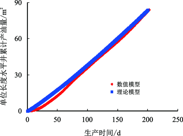 |
| 图14 注采压差60 kPa时累计产油量与时间关系 Fig. 14 The relationship between cumulative oil production per unit length and time when pressure difference is 60 kPa |
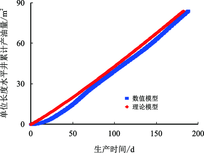 |
| 图15 注采压差80 kPa时累计产油量与时间关系 Fig. 15 The relationship between cumulative oil production per unit length and time when pressure difference is 80 kPa |
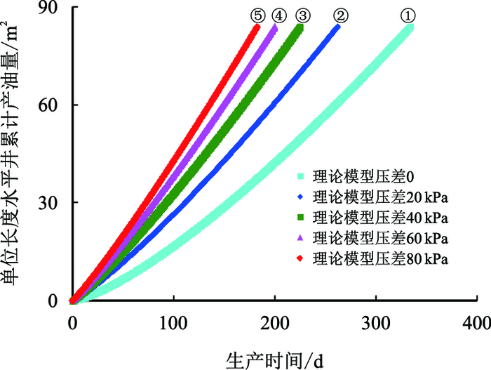 |
| 图16 不同压差下单位长度水平井累计产油量与时间关系 Fig. 16 The relationship between cumulative oil production per unit length and time on different injector-producer pressure difference |
从图 7~图 11中可以看出:随着注采压差的增大,产油速度开始逐渐增加,但是其增加的趋势逐渐变缓,其原因可能是当泄油斜面存在一定的压差时,重力作用无法驱动的稠油,在注采压差的作用下开始流动,但是随着压差的继续增大,除去可以驱动的部分加热稠油外,再大的注采压差也不能驱动蒸汽腔前缘受热较少的高黏稠油,所以会呈现出随着压差增大,开始采油速度增加明显,但是到后面增加变缓的原因。
图 12~图 15为不同注采压差下累计产油量,数值模型与理论模型的拟合示意图,可以看出其拟合效果较好。从图 16中可以看出:随着压差的增大,①②③④⑤五条拟合曲线中蒸汽腔到达油层顶部的时间分别为330,260,225,200,183 d,呈现递减的趋势,但是其减少的趋势逐渐变缓,其原因是:产油速度决定了蒸汽填充油层孔隙的速度,所以蒸汽到达油层顶部的时间与产油速度表现出了相同的规律。
同时,从图 11和图 16中还可以看出:在SAGD产能上升阶段,Butler的产能预测方法(拟合曲线①)与考虑注采压差(拟合曲线②③④⑤)时相对比,Butler的产能预测方法对单位长度水平井累计产油量和产油速度估计都过低,这也同时验证了Adegbesan的观点[15],即SAGD生产前期的产油速度远远高于Butler在纯重力预测下的产油速度。但是图 15中可以看出:当压差大于80 kPa后,拟合曲线出现了偏差,理论预测出来的产量比数模中高,其原因是压差过大后开始出现汽窜,因此注采压差不是越大越好,本文中最佳注采压差范围为60~80 kPa。
4 结论(1) SAGD生产过程中存在压差时开采效果更好,在Butler的基础上考虑压差驱替的作用,推导了考虑压差驱替的上产阶段产能预测模型。
(2) 通过该模型与数值模拟结果对比,证明该数学模型准确度较高,并且相比于数模具有更高的计算速度,便于现场的快速预测。
(3) 注采压差的存在会增加产油量和减少蒸汽腔到达油层顶部的时间,但是其增加及减少的趋势都随压差的增大而逐渐变缓,但这并不意味着注采压差越大越好,因为注采压差过大时会导致汽窜问题。
| [1] |
于连东. 世界稠油资源的分布及其开采技术的现状与展望[J].
特种油气藏, 2001, 8(2): 98–103.
YU Liandong. Distribution of world heavy oil reserves and its recovery technologies and future[J]. Special Oil and Gas Reservoirs, 2001, 8(2): 98–103. doi: 10.3969/j.issn.1006-6535.2001.02.029 |
| [2] |
马鸿, 陈振琦, 常毓文. 超稠油水平井注蒸汽开采数值模拟研究[J].
特种油气藏, 1998, 5(1): 19–22.
MA hong, CHEN Zhenqi, CHANG Yuwen. Numerical simulation study of steam injection development of super heavy oil with horizontal well[J]. Special Oil and Gas Reservoirs, 1998, 5(1): 19–22. |
| [3] |
刘志波, 程林松, 纪佑军, 等. 蒸汽与天然气驱(SAGP)开采特征:与蒸汽辅助重力泄油(SAGD)对比分析[J].
石油勘探与开发, 2011, 38(1): 79–83.
LIU Zhibo, CHENG Linsong, JI Youjun, et al. Production features of steam and gas push:Comparative analysis with steam assisted gravity drainage[J]. Petroleum Exploration and Development, 2011, 38(1): 79–83. |
| [4] |
马德胜, 郭嘉, 昝成, 等. 蒸汽辅助重力泄油改善汽腔发育均匀性物理模拟[J].
石油勘探与开发, 2013, 40(2): 188–193.
MA Desheng, GUO Jia, ZAN Cheng, et al. Physical simulation of improving the uniformity of steam chamber growth in the steam assisted gravity drainage[J]. Petroleum Exploration and Development, 2013, 40(2): 188–193. doi: 10.11698/PED.2013.02.07 |
| [5] |
高永荣, 刘尚奇, 沈德煌, 等. 氮气辅助SAGD开采技术优化研究[J].
石油学报, 2009, 30(5): 717–721.
GAO Yongrong, LIU Shangqi, SHEN Dehuang, et al. Optimization of N2 injection technology during steam assisted gravity drainage process[J]. Acta Petrolei Sinica, 2009, 30(5): 717–721. doi: 10.7623/syxb200905014 |
| [6] | ROGER, Butler. 重油和沥青的热力开采工艺[M]. 北京: 石油工业出版社, 1994. |
| [7] | BUTLER R M, STEPHENS D J. The gravity drainage of steam-heated heavy oil to parallel horizontal wells[J]. The Journal of Canadian Petroleum, 1981, 20(2): 90–96. doi: 10.2118/81-02-07 |
| [8] | BUTLER A. Rise of interfering steam chambers[J]. Journal of Canadian Petroleum Technology, 1987, 26(3): 70–75. doi: 10.2118/87-03-07 |
| [9] | BUTLER R M, MCNAB G S, LO H Y. Theoretical studies on the gravity drainage of heavy oil during in-situ steam heating[J]. Canadian Journal of Chemical Engineering, 1981, 59(4): 455–460. doi: 10.1002/cjce.5450590407 |
| [10] | CARDWELL W T, PARSONS R L. Gravity drainage theory[J]. Transactions of the Aime, 1949, 179(1): 199–215. doi: 10.2118/949199-G |
| [11] | BUTLER R M. A new approach to the modelling of steamassisted gravity drainage[J]. Journal of Canadian Petroleum Technology, 1985, 24(3): 42–51. doi: 10.2118/8503-01 |
| [12] | EDMUNDS N. On the difficult birth of SAGD[J]. JCPT, 1999, 38(1): 14–17. doi: 10.2118/99-01-DA |
| [13] | BUTLER R M. Some recent developments in SAGD[J]. Journal of Canadian Petroleum Technology, 2001, 40(1): 18–22. doi: 10.2118/01-01-DAS |
| [14] | ADEGBESAN K O, LEATTE R P, COURTNAGE D E. Performance of a thermal horizontal well pilot[C]. SPE 22892, 1991. doi:10.2118/22892-MS |
| [15] | EDMUNDS N R. Investigation of SAGD Steam Trap Control in Two and Three Dimensions[J]. Journal of Canadian Petroleum Technology, 1998, 39(1): 267–277. doi: 10.2118/00-01-02 |
| [16] | ITO Y, SUZUKI S. Numerical simulation of the SAGD process in the Hangingstone oil sands reservoir[C]. SPE 96-57. doi:10.2118/96-57 |
| [17] | ALI S M F. Is there life after SAGD?[J]. Journal of Canadian Petroleum Technology, 1997, 36(6): 20–23. doi: 10.2118/97-06-DAS |
| [18] |
陈元千. 对Butler双水平井SAGD产量公式的质疑[J].
断块油气田, 2015, 22(4): 472–475.
CHEN Yuanqian. Question of SAGD production rate formula for Butler's double horizontal wells[J]. Fault Block Oil & Gas Field, 2015, 22(4): 472–475. doi: 10.6056/dkyqt201504014 |
| [19] | REIS J C. A steam-assisted gravity drainage model for tar sands:linear geometry[C]. SPE 92-10-01, 1992. doi:10.2118/92-10-01 |
 2017, Vol. 39


